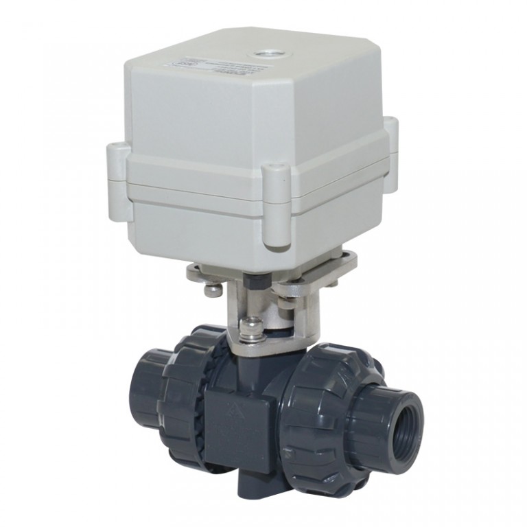
A150-T50-P2-B 2 inch DN50 PVC motorized valve true union with manual overrdie
| Xicheng Street, Xincheng Road No.1012,Huangyan Taizhou ,Zhejiang Province – 台州市 – 中国, 上海关闭 | +86-13676642305 | |
| http://www.motorized-valve.com | ||
Technical Parameters:
Valve size NPT/BSP/no thread socket type 2" DN50
Maximum working pressure 1.0 MPa
Circulation medium Fluid, air
Rated voltage DC12v, DC24v,AC/DC9-24, AC110-230v
Wiring control methods CR201 CR501 CR303 CR401 CR703 CR704 CR2-02 CR5-02
Working current ≤1A
Open/close time ≤15S
Life time 50000 times
Valve Body material PVC,UPVC,CPVC,PPH(Optional)
Actuator material Engineering Plastics
Sealing material EPDM & PTFE
Actuator rotation 90°
Max. torque force 10Nm(Optional)
Cable Length 0.5m,1.5m(Optional)
Environment temperature -15℃~50℃
Liquid temperature 2℃~55℃
Manual override Yes
Indicator Yes
Protection class IP67
No thread Socked type standard confirm
when you choose the PVC valve body No thread, please confirm you need which standard. see below picture choose you need.
1)ANSI 2)JIS 3)DIN 4)CNS
CR2 01 Wiring Diagram ( 2 wires control )
motorized valve wire control CR201
·RD connect with positive, the BK connect with negative, the valve closed, the actuator automatically power off after in place , the valve remains fully closed position .
·BK connect with positive, the RD connect with negative, the valve open, the actuator automatically power off after in place, the valve remains fully open position .
﹡Suitable Working Voltage: DC5V/DC12V/DC24V
﹡Exceeding the working voltage is forbidden
CR2 02 Wiring Diagram ( 2 wires control – Spring return in case of the power is failure)
motorized valve wire control CR202
·When SW is closed , the valve open. the actuator automatically power off after in place
·When SW is open, the valve closed, the actuator automatically power off after in place
﹡Suitable Working Voltage: AC/DC9-24V,AC/DC110V-230V,AC/DC9-35V(with manual override).
﹡Exceeding the working voltage is forbidden
CR3 03 Wiring Diagram (3 wires control)
motorized valve wire control CR303
·RD& GR connect with positive, the BK connect with negative
·SW CLOSED, the valve OPEN, the actuator automatically power off after in place
·SW OPEN, the valve CLOSED, the actuator automatically power off after in place.
﹡Suitable Working Voltage: AC/DC9-35V/AC110-230V
﹡Exceeding the working voltage is forbidden
CR4 01 Wiring Diagram (4 wires control )
motorized valve wire control CR401
1、RD & BK are connected to the power, WT & YW are connected to the controlled wiring.
2、When the SW is closed , the valve open
3、When the SW is open , the valve closed Suitable Working Voltage::AC/DC110V-230V
Exceeding the working voltage is forbidden
The control wiring with power DC5V , when muitiple motorized valves are working in paralled , must put the same
color control wiring together, otherwise the valve could working normally .
CR5 01 Wiring diagram ( with feedback signal)
motorized valve wire control CR501
1. RD connect with positive, the BK connect with negative,the valve closed, the actuator automatically power off after in place .
2 BK connect with positive, the RD connect with negative,the valve open, the actuator automatically power off after in place .
3 GR & WT are connect when the valve open fully, YW & WT are connect when the valve closed fully
Suitable Working Voltage::DC5V/DC12V/DC24V
Exceeding the working voltage is forbidden
CR5 02 Wiring diagram ( with feedback signal)
motorized valve wire control CR502
·When SW is closed , the valve open. the actuator automatically power off after in place
·When SW is open, the valve closed, the actuator automatically power off after in place
﹡BL & WT are connect when the valve open fully, YW & WT are connect when the valve closed fully
﹡Suitable Working Voltage: AC/DC9-24V, AC/DC9-35V, AC/DC110V-230V
﹡Exceeding the working voltage is forbidden
CR7 04 Wiring Diagram ( 7 wires control with feedback signal )
motorized valve wire control CR703
·RD & BK are connected to the power, GR & GY are connected to the controlled wiring.
·When the SW is closed , the valve open
·When the SW is open , the valve closed
·BL & GY connect with the valve's fully open signal wiring
·YW & WT connect with the valve's fully closed signal wiring.
Suitable Working Voltage::AC/DC110V-230V
Exceeding the working voltage is forbidden
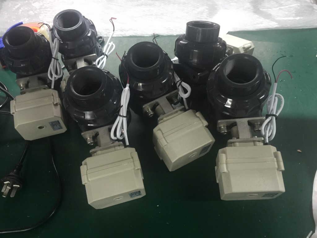
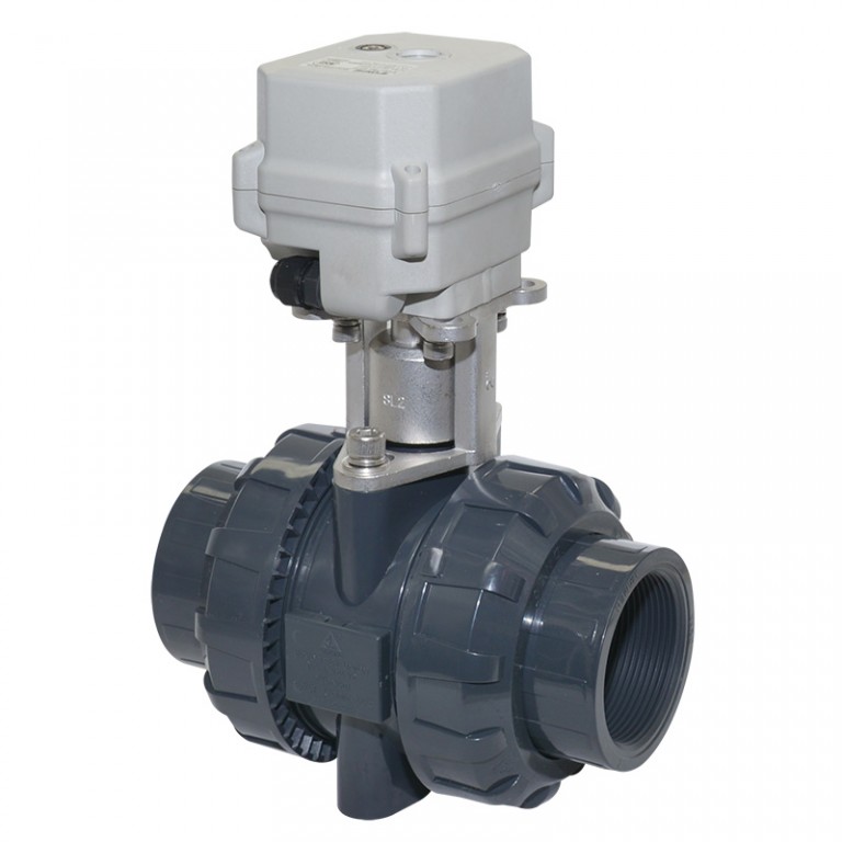
A150 motorized valve with manual override new feature
motorized valve with manual overridemotorized valve with manual override
When you inquiry the valve, pls confirm the detail technical data :
1)valve size
2)material, brass or stainless steel or PVC?
3)working voltage
4)wiring diagram
5)thread BSP or NPT or no thread(which standard)?
6)quantity?
7)cable length, 0.5m is OK for you?
TaizhouTonhe flow control equipment Co., Ltd.
Activity: